Authors: Stephen Nageotte, MD; Evan Zahn, MD
How I do it: Tips, Tricks, and Techniques
A PICS Society education
Implantation of the Alterra Adaptive Prestent and SAPIEN 3 valve for Transcatheter Pulmonary Valve Replacement
The Alterra Adaptive Prestent (AAP) (Edwards Lifesciences, Irvine, CA) is an FDA-approved device designed to prepare the right ventricular outflow tract (RVOT) for a 29 mm SAPIEN 3 balloon expandable valve for those patients meeting criteria for Transcatheter Pulmonary Valve Replacement (TPVR). This device works by internally remodeling the RVOT to create a suitable landing zone for a 29mm SAPIEN 3 valve in those patients in whom a balloon expandable valve alone would not suffice due to the large size and/or irregular nature of the RVOT. It has a self-expanding nitinol frame with PET covering all cells except the distal outflow cells (Figure 1). The uncovered cells allow the device to be placed high in the main pulmonary artery, across the pulmonary artery bifurcation, to maintain unobstructed blood flow to the branch pulmonary arteries.
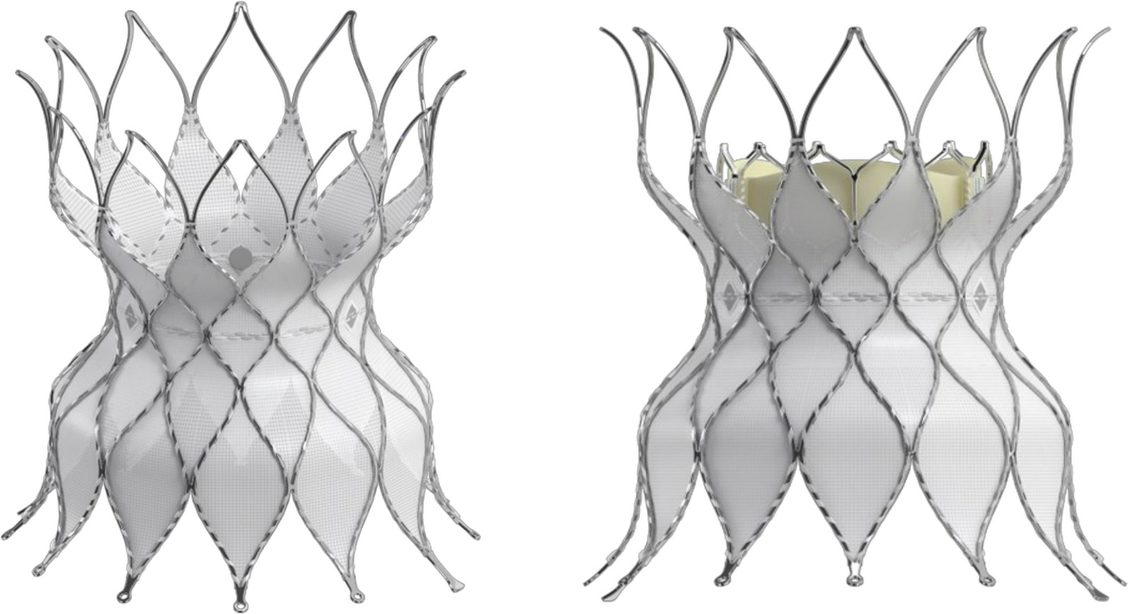
Figure 1: Alterra Adaptive Prestent
The inflow and outflow diameters of the device measure 40 mm, and the central waist, demarcated with 3 radiopaque markers, measures 27 mm to accommodate the 29 mm SAPIEN 3 valve. The total Prestent length is 48 mm, with a covered length of 30 mm, which allows the treatment of patients with a shorter RVOT without the need to place a significant amount of the inflow portion of the device within the muscular infundibulum. 1
The AAP comes loaded in a delivery system with a handle, outer shaft covering the stent that is retracted for delivery, inner delivery shaft with the AAP pre-mounted, and a tapered tip to improve maneuverability through the vasculature (Figure 2).
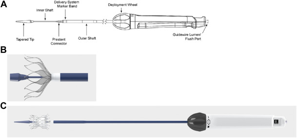
Figure 2: Alterra Delivery System
The delivery handle utilizes an ergonomic knob for a slow, controlled deployment. Importantly, AAP can be recaptured up to 70% deployment, allowing for repositioning of the prestent.2 The entire system fits through a 16 Fr eSheath (Edwards Lifesciences, Irvine, CA), though many operators utilize a larger DrySeal sheath (Gore Medical, Flagstaff, AZ). Following implantation of the AAP, the 29 mm SAPIEN 3 valve is mounted on a Pulmonic Delivery System (Edwards Lifesciences, Figure 3) and delivered into the AAP.
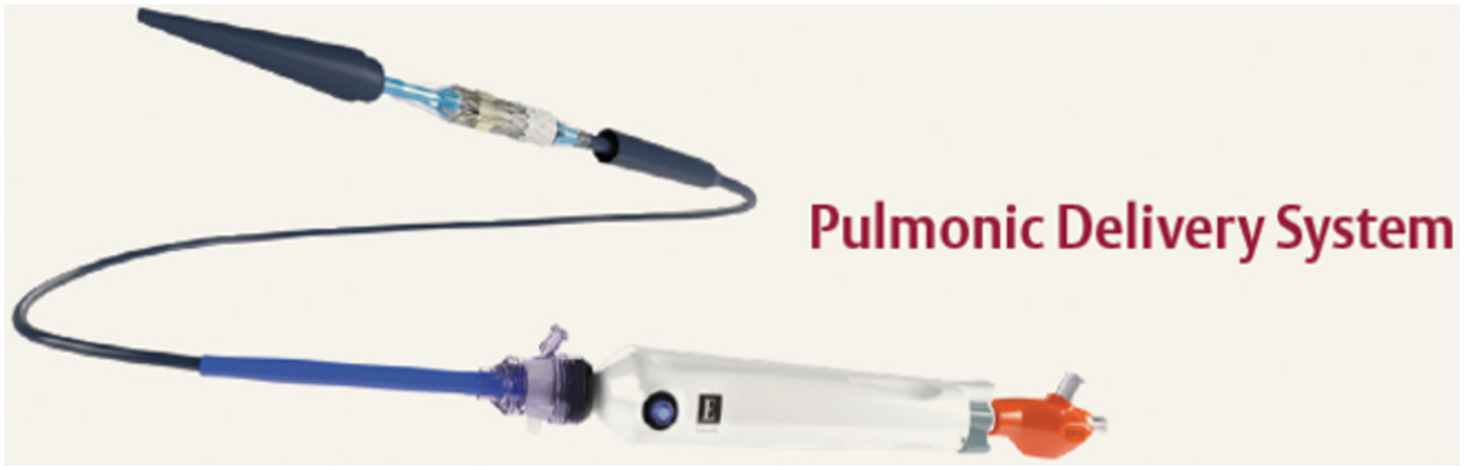
Figure 3: Pulmonic Delivery System
The implantation of an Alterra Adaptive Prestent followed by a SAPIEN 3 valve for TPVR requires precise planning and technique. This guide aims to provide insights and practical tips to enhance procedural success, drawing from established best practices as well as our 8-year institutional experience.
Comprehensive Patient Evaluation
Anatomical Assessment: The screening for candidacy for an AAP is performed through data obtained from an ECG-gated CTA. These are detailed reports and include perimeter plots (both systolic and diastolic are provided) assessing coaptation between the inflow and outflow portions of the AAP and the patient-specific anatomy, virtual AAP implants in multiple potential locations, assessments of the branch PAs and coronary arteries, and suggested optimal gantry angles for the procedure (Figure 4).
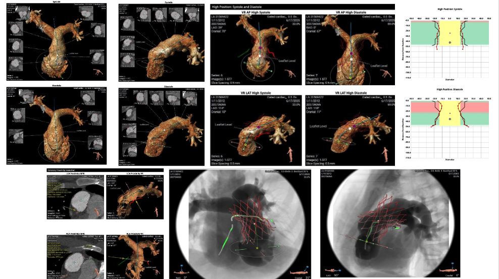
Figure 4: Alterra Screening Report
In analyzing the anatomy, one should mentally plan the procedure in advance. These decisions include the preferred branch pulmonary artery (PA) guide wire placement to optimize AAP alignment with the RVOT and ease of delivery, as well as goal implant location in the RVOT and whether the implant will be entirely supra-annular or cross the annulus. Our practice in nearly all cases is to place the AAP with the inflow portion of the device just at or slightly below the previous pulmonary valve annulus, attempting to avoid annular implants that leave a considerable portion of the device in contact with the infundibular myocardium. We believe this may have several advantages including: decreased incidence of peri-procedural ventricular ectopy, allowing for future access to the infundibular isthmus region for ablation if needed, and potentially simpler surgical intervention if needed in the future.
Patient Specific Criteria: Beyond the screening report, one must consider factors such as previous cardiac interventions (e.g., presence of an ostial branch PA stent), the presence of comorbidities, and the patient's overall health status. The goal of any procedure should be to make the best decision for the patient's lifelong care, considering all available options. If deemed feasible, it is our practice to implant a SAPIEN 3 valve alone if the anatomy is favorable for a balloon-expandable valve.
Team Dynamics: It's important to assemble a multidisciplinary team to ensure comprehensive care for your patient. Involvement of the entire heart center (interventional cardiologists, cardiac surgeons, imaging specialists, and anesthesiologists) in the planning phase will optimize buy-in from all stakeholders and maximize long-term care and outcomes. Regular briefings and role definition are crucial. Having these discussions outside the laboratory before a crisis will provide the best chance of successfully navigating complications.
Case Discussion: Ensure that all team members are aware of what this procedure entails so that complications can be identified early and difficulties can be mitigated.
Alterra Adaptive Prestent Placement
Once a patient is deemed to be a good candidate based on the screening report, typically no further testing is needed. However, flexibility during the procedure and the ability to adapt and alter the initial plan are critical to maximizing the chance of a successful implant. The femoral vein (FV) is most typically the preferred access site for the valve implant, but individual patient anatomy (e.g., previous vascular stenoses/ occlusions, tortuous RVOT) must be considered. If tracking of catheters proves to be difficult, the right internal jugular vein is a good option. Our standard initial vascular access consists of 11 Fr. RFV, 5 Fr. RFA, and 7 Fr. LFV. Once vascular access has been completed, all patients receive intravenous prophylactic antibiotics as well as systemic intravenous heparin. Serial ACT measurements are made every 30 to 45 minutes to keep them in the 250s range.
Prior to performing the hemodynamic and angiographic catheterization, it is our practice to perform a complete intracardiac echocardiogram (ICE) to assess the preprocedural degree of tricuspid regurgitation, the presence or absence of any interatrial communication, and the pre-interventional status of the right ventricular outflow tract, focusing on the presence or absence of native leaflets and their location in relation to the potential landing zone.
Video 1a: Baseline ICE imaging of tricuspid valve
Video 1b: Baseline ICE imaging of RVOT
After obtaining baseline hemodynamics using a 7 Fr. balloon-tipped endhole catheter via the RFV, the wire position is attained in a deep, posterior branch with a Lunderquist 0.035” guide wire. In most (but not all) anatomies, the right pulmonary artery is preferred over the left as it provides better alignment of the APP with the RVOT. Importantly, a balloon-tipped end-hole catheter should always be used to navigate the right heart to ensure the tricuspid valve is crossed between leaflets rather than risking chordal disruption.
After the stiff guide wire has been placed, an ascending aortogram +/- selective coronary arteriograms may be performed if there are concerns regarding the proximity of the coronary arteries and the intended region of the valve implant. We decide whether this angiogram is necessary on a case-by-case basis. A 7 Fr. Berman angiographic catheter is then advanced via the LFV to the distal main pulmonary artery, and a dense injection is performed using gantry angles predetermined from the CT scan to maximize anatomical understanding of the MPA and RVOT. Areas of focus on this injection include the undersurface of the takeoff of the RPA, the MPA anatomy, presence or absence of remnant valve leaflets and where the MPA transitions in the muscular RVOT.
Video 2: MPA angiogram with wire in position
Typically, a team conversation about the desired location of the Alterra implant takes place at this time. Preparing the Alterra simply involves removing it from its packaging and flushing the side port and wire lumen. The 11 Fr. RFV sheath is replaced with a 24 Fr. DrySeal sheath and the Alterra is advanced over the guide wire into the desired location, typically just distal to the final landing zone. An angiogram may be performed at this point as the delivery system may alter the pertinent anatomy.
Depending on the anatomy (primarily the length of the MPA), we begin deploying the Alterra by slowly rotating the delivery knob counterclockwise either in the proximal RPA or distal MPA.
Video 3: Uncovering the initial 25% of device
Approximately 25-30% of the device is revealed, and another angiogram is performed.
Video 4: Angiogram with 25% Deployment
If initial deployment is in the proximal RPA, the entire system is then gently retracted over the wire, allowing the outflow of the Alterra to “flower” open into the distal MPA. At this point, we take another angiogram to determine stent position in relation to the PA bifurcation as well as the angulation of the distal apices to the distal MPA (see below on potential complications).
Video 5: 50% Deployment
Additional adjustments may be made to the device position by further retracting the entire system towards the RVOT as deemed appropriate. Note, we do not recommend advancing the uncovered Alterra prestent distally. Once the final position is achieved, the Alterra is fully deployed by completing the retraction of the outer covering.
Video 6: Alterra full deployment
Following release from the delivery system, the operator should ensure that both proximal retention tabs of the device are free. It is our preference to perform an angiogram after the Alterra implant prior to the delivery system removal.
Video 7: Angiogram post-Alterra deployment
The delivery system is then removed over the guide wire, making sure that the distal portion of the delivery system does not interact with the apices of the device by maintaining coaxial position through the center of the prestent.
Video 8: Removal of Alterra delivery system
SAPIEN Valve Deployment
As the 29 mm SAPIEN 3 valve is being mounted onto the Pulmonic Delivery System (PDS), the gantry angles are adjusted to profile the central waist of the Alterra in at least 1 plane. The 24 Fr. DrySeal sheath and 7 Fr. Berman angiographic catheter in the LFV are removed. The PDS is advanced over the Lunderquist wire directly through the skin and the short in-line sheath that comes with the PDS is advanced into position in the RFV to maintain hemostasis. The PDS is advanced over the wire and into position within the RVOT, such that the valve is located in the midportion of the Alterra utilizing the radiopaque markers on the Alterra as a target.
Video 9: Advancement of PDS
Slow retraction of the outer sheath of the PDS results in uncovering of the SAPIEN 3. This should be done slowly to maintain the valve in a stable position.
Video 10: Uncovering the PDS
The valve is then deployed in the standard manner using slow inflation to nominal volume3.
Video 11: Deployment of SAPIEN 3
Using a similar coaxial approach as Alterra, the PDS is removed over the wire to the mid-IVC.
Video 12: PDS removal
In the mid-IVC, under fluoroscopic guidance, maintaining wire position, the outer PDS sheath is advanced, recovering the balloon until it remarries with the back of the nosecone. The entire system, including the in-line sheath, is then removed over the guide wire and replaced with the 24 Fr. DrySeal sheath. We typically then advance a 5 Fr. pigtail catheter over the guide wire, take a PA pressure, perform a PA angiogram, and get a RV and RA pressure, taking care not to drag the pigtail catheter across the freshly implanted valve.
Video 13: Angiogram after valve deployment
Following this, it is our practice to perform follow-up ICE imaging where we evaluate any change in tricuspid regurgitation, SAPIEN valve leaflet function, and the presence or absence of any valve or para-valvular regurgitation.
Video 14a, Post-Valve ICE Imaging, evaluating tricuspid valve and pulmonary valve
Video 14b: Post-Valve ICE Imaging, evaluating pulmonary valve
Once this is complete, all sheaths and catheters are removed from the groin and hemostasis is obtained with a combination of manual pressure on the smaller access sites and tightening down of the two previously placed Perclose sutures in the valve delivery site.
Monitoring and Follow-up
Immediate Post-Operative Assessment: All patients are kept in the house on a telemetry-monitored bed overnight. It is common for these patients to have frequent premature ventricular contractions after their procedure, and if these are felt to be significant, we will start them on oral beta blockers. Since we have altered our practice to placing the vast majority of these devices in a supra-annular position, we have noted a marked decrease in quantity, severity, and duration of post-procedural ventricular ectopy. More significant ectopy or vital sign instability should prompt stat evaluation of the valve with an x-ray and echocardiogram, and potentially a CTA. In the morning, all patients receive an echocardiogram and an electrocardiogram prior to discharge. A new pericardial effusion should warrant further evaluation of the device with a CTA. All patients at our institution are currently discharged on dual antiplatelet therapy for a minimum of three months, and all are instructed to follow subacute bacterial endocarditis prophylaxis for the lifetime of the valve.
Long-term Monitoring: These patients require lifelong follow-up with continued evaluation of the valve function and right heart parameters. If a significant change is noted in the degree of valve regurgitation or stenosis, our institutional approach is to obtain a 4D CT scan to evaluate for the presence of valve leaflet dysfunction secondary to the presence of microthrombi, which, if present, would prompt a change in antithrombotic therapy.
The Alterra Adaptive Prestent has been implanted in over 1500 patients with excellent medium-term results and low rates of complications. However, a key to managing these patients is the anticipation and early detection of complications.4 As of this writing, we are aware of 4 known cases of acute perforation of the Alterra apices through the distal MPA resulting in hemopericardium.5 All cases were recognized prior to hospital discharge, and all patients underwent surgical removal of the device successfully. It is currently believed that this rare complication can be mitigated by ensuring alignment of the device to the curvature of the main pulmonary artery.
While positioning and uncovering the AAP, special focus should be drawn to the alignment of the distal apices of the AAP with the RVOT. If the AAP starts to deploy such that the distal apices are canted leftward (Figure 5) and/or inferiorly, it should be recaptured, and an alternative strategy for deployment should be sought.
Video 15a: Malaligned initial deployment (AP)
Video 15b: Malaligned initial deployment (Lateral)
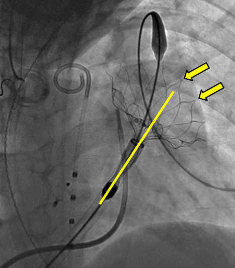
Figure 5: Malaligned initial deployment (AP)
If the prestent is felt to be too low, the prestent may be recaptured: It can then be redeployed using alternative strategies (e.g., change wire position or landing zone).
Video 16a, Alterra recapture, AP
Video 16b: Alterra recapture, lateral:
Video 17a: Partial re-deployment of AAP with wire repositioning to RPA
Video 17b: Complete re-deployment of AAP with wire repositioning to RPA
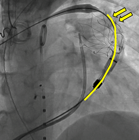
Figure 6: Redeployment of AAP, highlighting appropriate stent alignment within RVOT
Of note, the prestent is easily recaptured when ≤70% deployment, allowing the operator multiple attempts to obtain ideal position.
To date, we are unaware of any instance of chronic erosion resulting in clinical sequelae despite notable concerns about the appearance of the depth of embedment of the device apices into the anatomy6. Whether this CT appearance of the device is a desirable design feature which allows for precision placement or is a risk for future vascular disruption remains to be seen, but certainly warrants follow-up and discussion.
The success of an Alterra Adaptive Prestent and SAPIEN 3 valve implantation hinges on meticulous planning, precise execution, and comprehensive post-procedural care. By integrating these tips and tricks, clinicians can achieve improved outcomes and patient satisfaction.
1. Patel ND, Levi DS, Cheatham JP, Qureshi SA, Shahanavaz S, Zahn EM. Transcatheter Pulmonary Valve Replacement: A Review of Current Valve Technologies. J Soc Cardiovasc Angiogr Interv. 2022;1(6):100452. doi:10.1016/j.jscai.2022.100452
2. Zahn EM, Chang JC, Armer D, Garg R. First human implant of the Alterra Adaptive PrestentTM: A new self-expanding device designed to remodel the right ventricular outflow tract. Catheter Cardiovasc Interv. 2018;91(6):1125-1129. doi:10.1002/ccd.27581
3. Shahanavaz S, Zahn EM, Levi DS, et al. Transcatheter Pulmonary Valve Replacement With the Sapien Prosthesis. J Am Coll Cardiol. 2020;76(24):2847-2858. doi:10.1016/j.jacc.2020.10.041
4. Stefanescu Schmidt AC, Bloom JP, Zahn E. Balancing New Technology With Rigorous Reporting of Complications. JACC Case Rep. 2025;30(6_Part_1):103558. doi:10.1016/j.jaccas.2025.103558
5. Complications From Transcatheter Pulmonary Valve Replacement With Self-Expanding Prestent. doi:10.1016/j.jaccas.2024.102836
6. Gillespie MJ, Maschietto N, Aboulhosn JA, Balzer DT, Qureshi AM, McElhinney DB. Extravascular protrusion of the Alterra adaptive prestent identified on surveillance computed tomography imaging. Catheter Cardiovasc Interv. 2024;104(2):256-263. doi:10.1002/ccd.31147